Skip to product information


$19.00
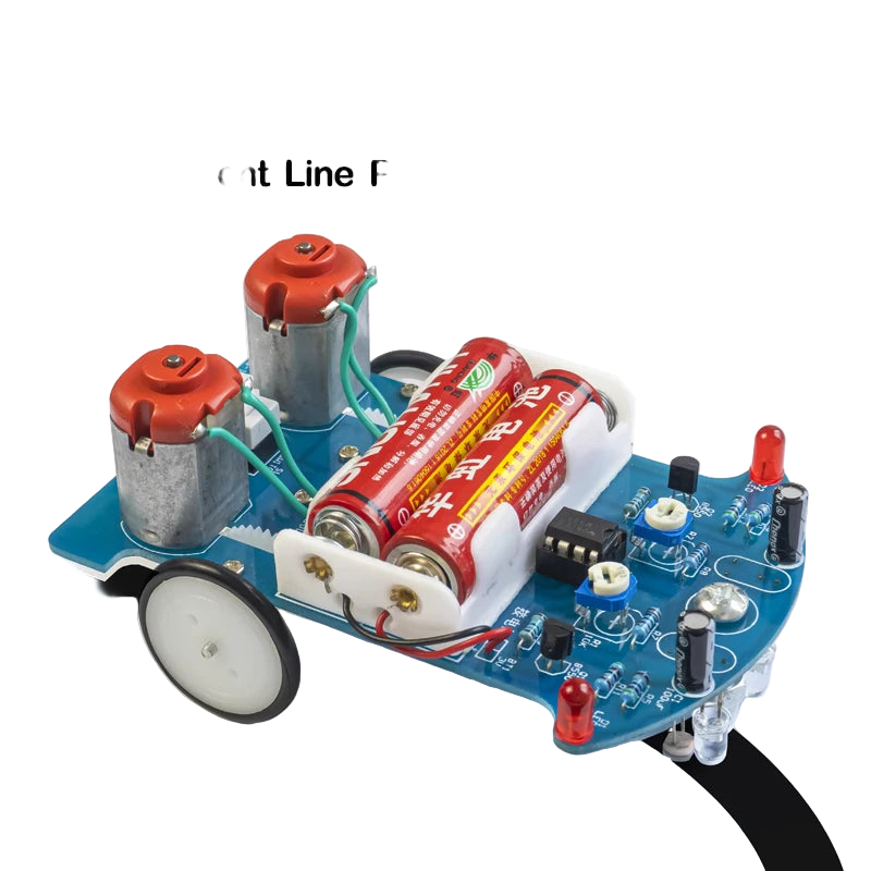
Intelligently follows a programed track patter. This electric circuit board kit is a great mini challenge.
Intelligent Tracking Car: Design and Assembly
This intelligent tracking car uses a photosensitive resistance circuit to compare light intensity from two sensors. When an imbalance is detected (e.g., one sensor detects a dark surface like a black line), the system instantly stops one motor while accelerating the other, allowing the car to adjust its direction and return to the correct path. This closed-loop system ensures rapid and precise control. The goal of this project is to simplify complex principles for educational purposes. During assembly, you will become familiar with mechanical principles and learn about key electronic components, including photosensitive resistors, voltage comparators, and motor drive circuits. Photosensitive Resistance Device Photosensitive resistors detect external light intensity. The stronger the light, the lower the resistance; the weaker the light, the higher the resistance. When a red LED projects light onto a surface (e.g., a white track with a black line), the differing reflection rates cause significant changes in the resistance of the photosensitive resistors, enabling precise control in the circuit.
Voltage Comparator Circuit
The circuit uses a dual voltage comparator integrated circuit, consisting of two independent precision voltage comparators. This component compares two input voltages and adjusts the output voltage level based on their relative values. The output is either high (near the supply voltage) or low (near ground). The comparator uses an open-collector output, requiring pull-up resistors to achieve a high output level. DC Motor with Gear Reduction. The car’s DC motors are equipped with gear reduction to control speed and torque. Without reduction, the car would move too quickly to control effectively, and the torque would be insufficient for reliable operation. The integrated gear reduction simplifies manufacturing and is well-suited for this application. Assembly Steps:
Step 1: Circuit Board Soldering The soldering process is straightforward but requires care. Solder components in order of height, starting with the lowest:
- Solder the eight resistors, verifying each with a multimeter to ensure proper connections.
- Solder polar components (e.g., transistors, LEDs, electrolytic capacitors), ensuring correct polarity. For LEDs, the longer pin is positive. For capacitors, the shorter pin is negative, as indicated by the PCB silkscreen.
- Avoid prolonged soldering to prevent damage to components.
- Components D4, D5, R13, and R14 can be skipped initially. The integrated circuit chip can be inserted later.
- After soldering, inspect the board carefully to avoid errors or poor connections.
Step 2: Mechanical Assembly
- Attach the universal wheel by inserting its screw into the designated PCB hole and securing it with a nut.
- Affix the battery box to the PCB using double-sided adhesive tape. Pass the battery leads through the reserved PCB holes, connecting the red wire to the 3V positive power supply and the yellow wire to ground.
- Assemble the wheels, each consisting of three black acrylic discs. Remove the protective film before assembly. The inner disc has a larger center hole, the middle disc has a smaller diameter, and the outer disc has a circular hole. Secure the three discs with screws and nuts, then attach the wheel to the motor shaft using black self-tapping screws. Fit the silicone rubber tire over the wheel.
- Glue the motor and wheel assembly to the designated PCB position, ensuring sufficient clearance between the wheels and the PCB edge. Solder the motor leads to the PCB, leaving enough lead length to allow for potential rewiring if the motor direction needs adjustment.
Step 3: Optoelectronic Circuit Installation Install the photosensitive resistors and LEDs (noting polarity) on the PCB in a reversed orientation, approximately 5mm above the ground. Maintain a 5mm gap between the photosensitive resistors and LEDs. Conduct an electrical test after installation. Step 4: Vehicle Debugging
- Insert two AA batteries into the battery box and set the switch to “ON.” The car should move forward in the direction of the universal wheel.
- Test the tracking function: covering the left photosensitive resistor should cause the right wheel to rotate, and covering the right resistor should cause the left wheel to rotate.
- If the car moves backward, swap the wiring of both motors simultaneously. If only one side moves incorrectly, swap the wiring for that motor.
Product info:
- Supply Voltage: DC3V
- Type: Voltage Regulator